Blender extensions · Blender 5.2+

Technical design, right inside Blender.

FORMLYNX is a family of Blender extensions for frames, machines and installations – exact to the millimetre, with bills of materials and files your CAD program and your workshop understand.

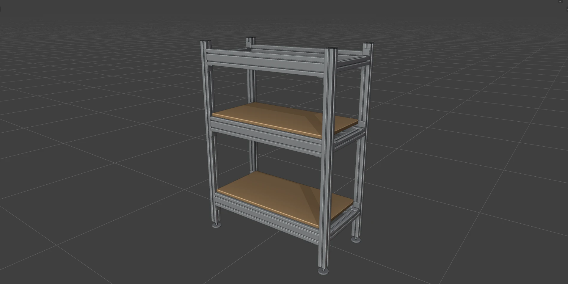
A shelf of aluminium profiles with levelling feet and two wooden shelf panels, built with MODULYNX in Blender
A shelf built with MODULYNX 1.0 in Blender – profiles, feet and panels, ready for the bill of materials.
The family

One way of working, tool by tool

Each FORMLYNX product is its own extension. They share one core, so parts, connection points and bills of materials fit together when you use more than one. One is available today, one is in development, more are planned.

Available · Version 1.0

Racks, workbenches, enclosures and machine frames from aluminium profiles. Click a node and the part snaps into place.

  • Box tool, panels, components with their own connection nodes
  • Connected parts follow when you change the frame
  • Bill of materials with weights and prices, STEP and DXF export
In development · prototype

Cables, wire harnesses and hoses laid through your model like in a CAD harness tool – with minimum bend radius and exact lengths.

  • Wires and multi-core cables routed through segments automatically
  • Bundle diameter, bend radius and cut lengths per wire
  • Plugs into MODULYNX connection nodes

Planned

Next in the family. Not in development yet – no release dates, and what each one does can still change. Tell us on Discord which one you need first.

Planned

Assemblies and bills of materials across all FORMLYNX products in one place.

Planned

Getting your parts ready for the workshop and for production.

Planned

Product images and presentations straight from your design.

FORMLYNX Core is the shared technical foundation: STEP and DXF writers, one bill-of-materials format across products, and connection points that one product can offer to another.

Modular design. Made simple. Design racks, workbenches, enclosures and machine frames from aluminium profiles – exact to the millimetre.

Get MODULYNX on Gumroad
3clicks to a complete frame box
27connection nodes per profile
1 mmexact – 10 mm grid, typed values
STEP · DXFfor CAD and laser cutting, plus bill of materials
MODULYNX 1.0

Click a node. The part snaps into place.

Every clip below is the real add-on running in Blender.

Box & panelsA frame in three clicks

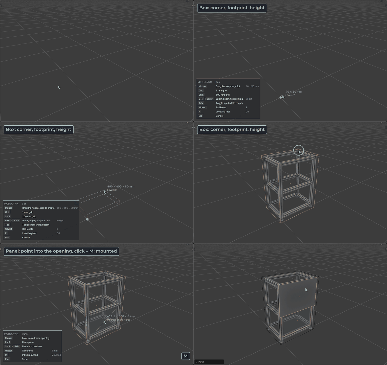
Click a corner, drag the footprint, drag the height – posts, rails and levelling feet arrive as one assembly. The mouse wheel sets the number of rail levels. Then point into an opening: infill panels go into the slots, M mounts them on the frame.

Box tool and panel tool in action

ConnectionsConnected parts follow

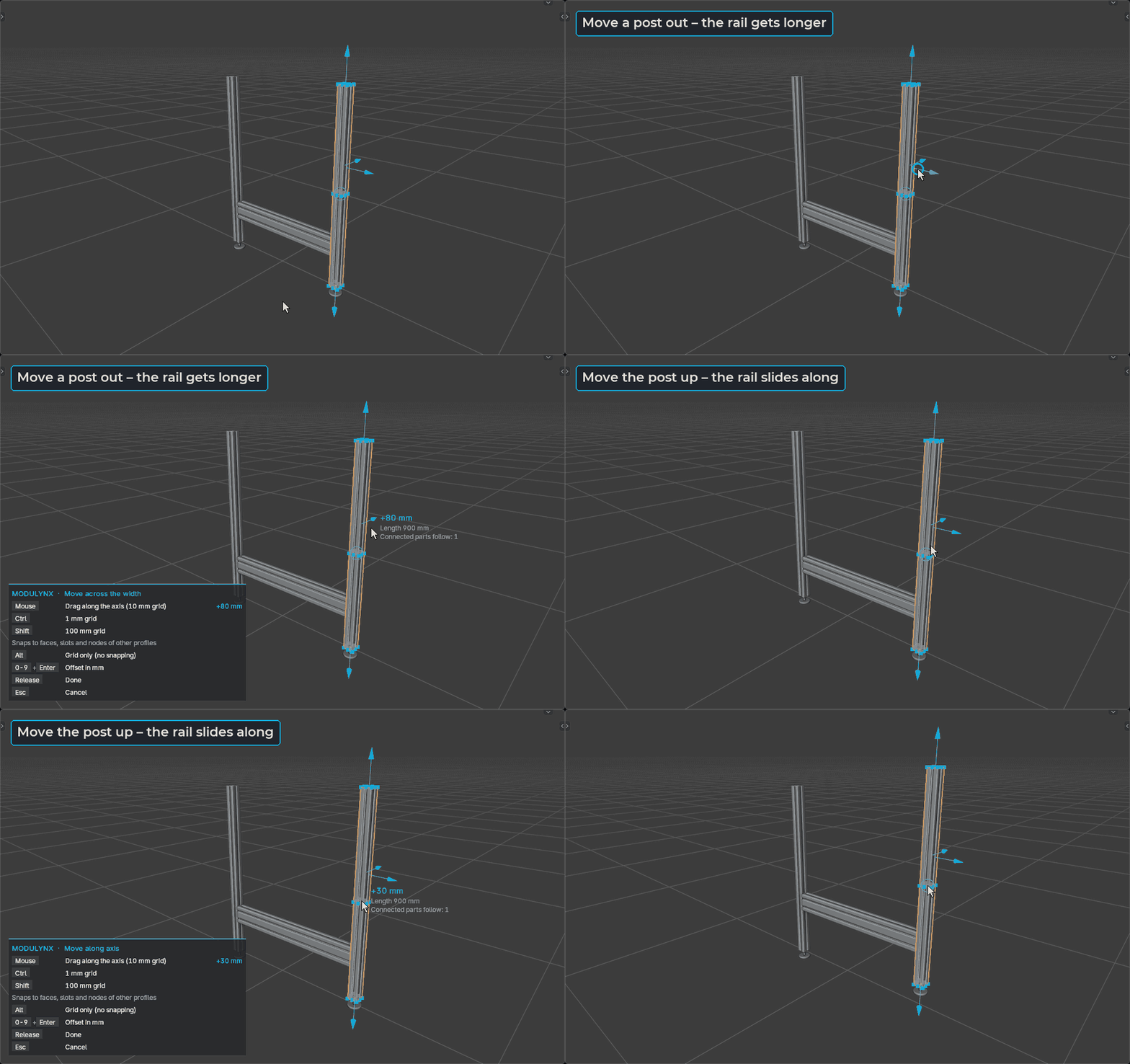
MODULYNX remembers which part rests on which profile. Move a post away and the rail between the posts gets longer; move it up and the rail slides along. Live while you drag.

Moving a post with the handles while the rail between the posts follows

HandlesDrag length and position directly

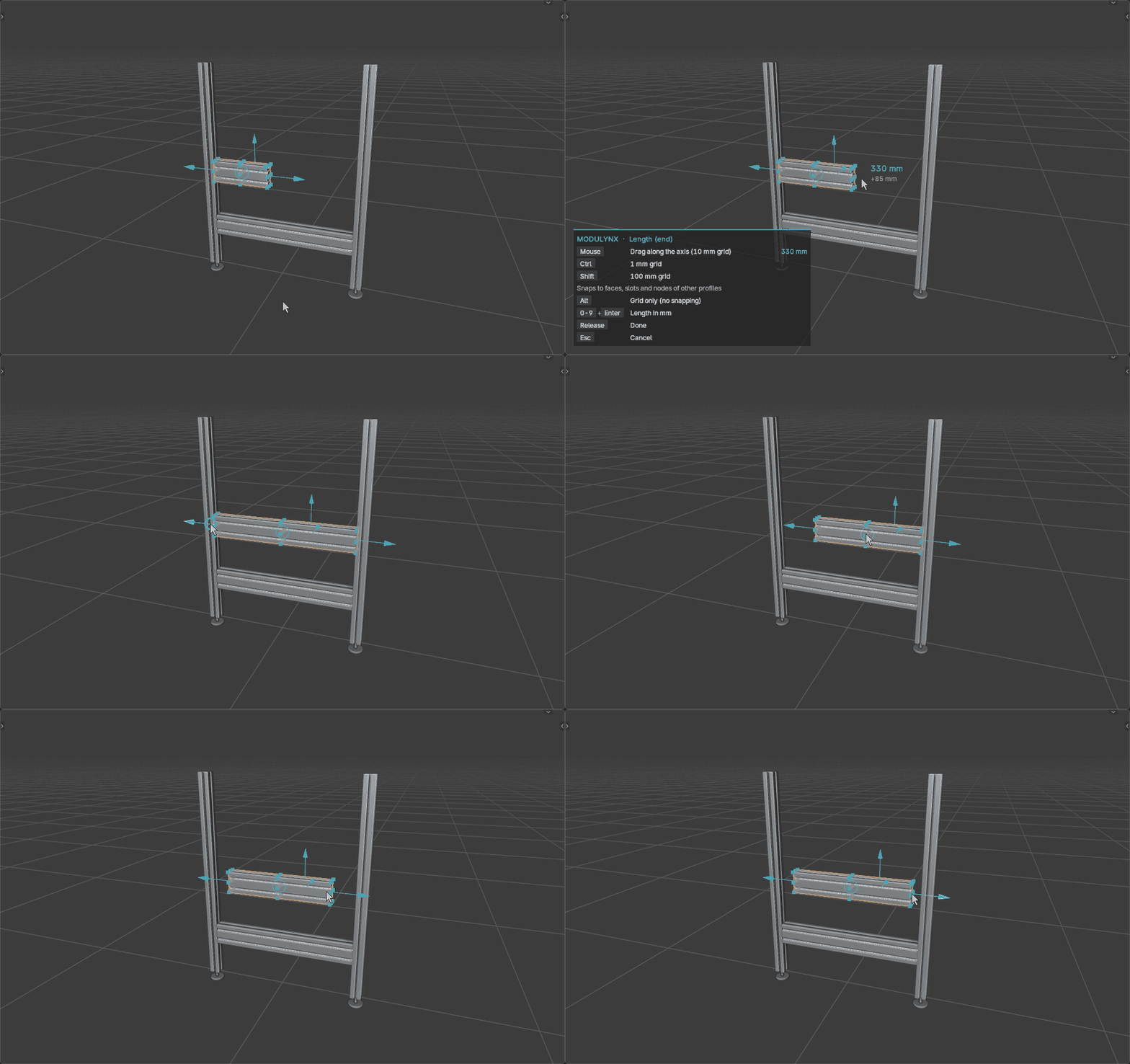
Arrows at the end faces change the length, the ring and the side arrows move the profile along and across. It snaps flush to neighbouring profiles, rests against them or centres on a slot. Type a number for the exact value.

Dragging a rail with the handles: flush with the post top, resting on the lower rail, centred on the slot

ComponentsPlates, holders, brackets – with their own nodes New

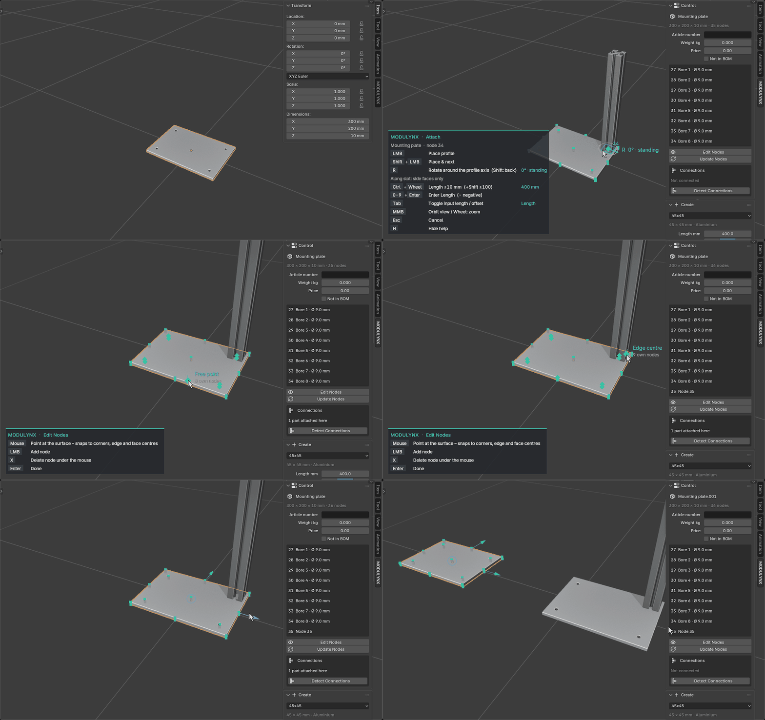
Turn any mesh into a component: it gets the node grid of its size plus a node at every bore, found automatically. Click on the surface to add your own nodes. Attach profiles to it, move it with the handles and everything attached follows. Save it to your component library and add it to any file.

A mounting plate becomes a component with nodes at its bores, a profile is attached to a bore and a copy is added from the library

AttachNew profiles snap to any node

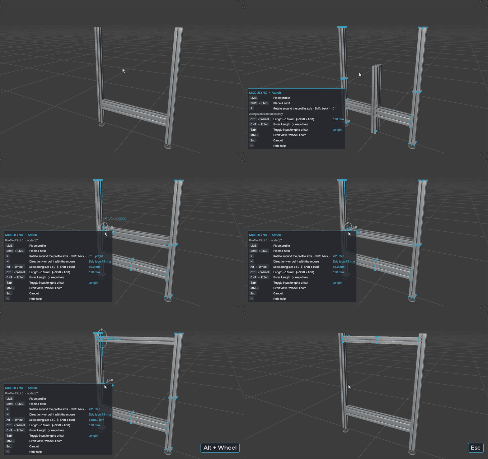
Point at a node and click – the profile attaches with its end face, correctly aligned and flush with the end of the profile it sits on. R rotates in 90° steps, Alt+wheel slides along the slot, Shift+click keeps going.

Attaching profiles to a post by clicking connection nodes

Span & slideLengths that follow, positions you can type

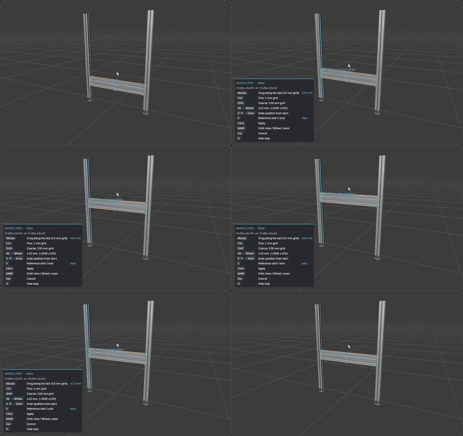
Span a profile between two nodes and the length is set for you. Slide a cross beam along its post on a 10 mm grid with a live ruler, or type the exact position.

Sliding a cross beam along the slot with a live measurement

Hardware & assembliesFeet, end caps and brackets in one click

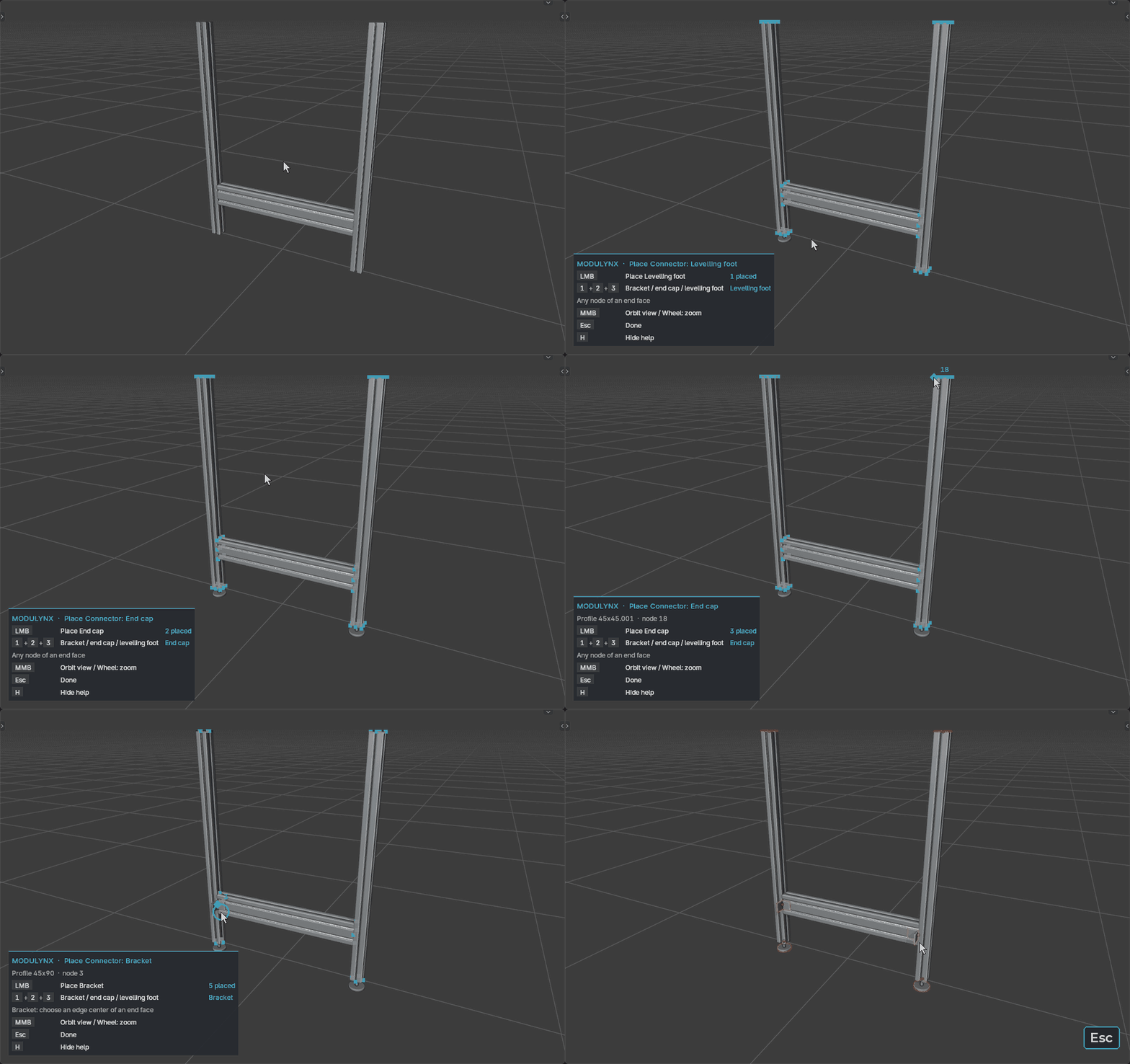
Connectors follow their profile. Group parts into an assembly, mirror them, or repeat them as a row – drag the spacing, the wheel sets the number of copies.

Placing levelling feet and end caps on profile end faces

Cross-section editorAny profile, your way

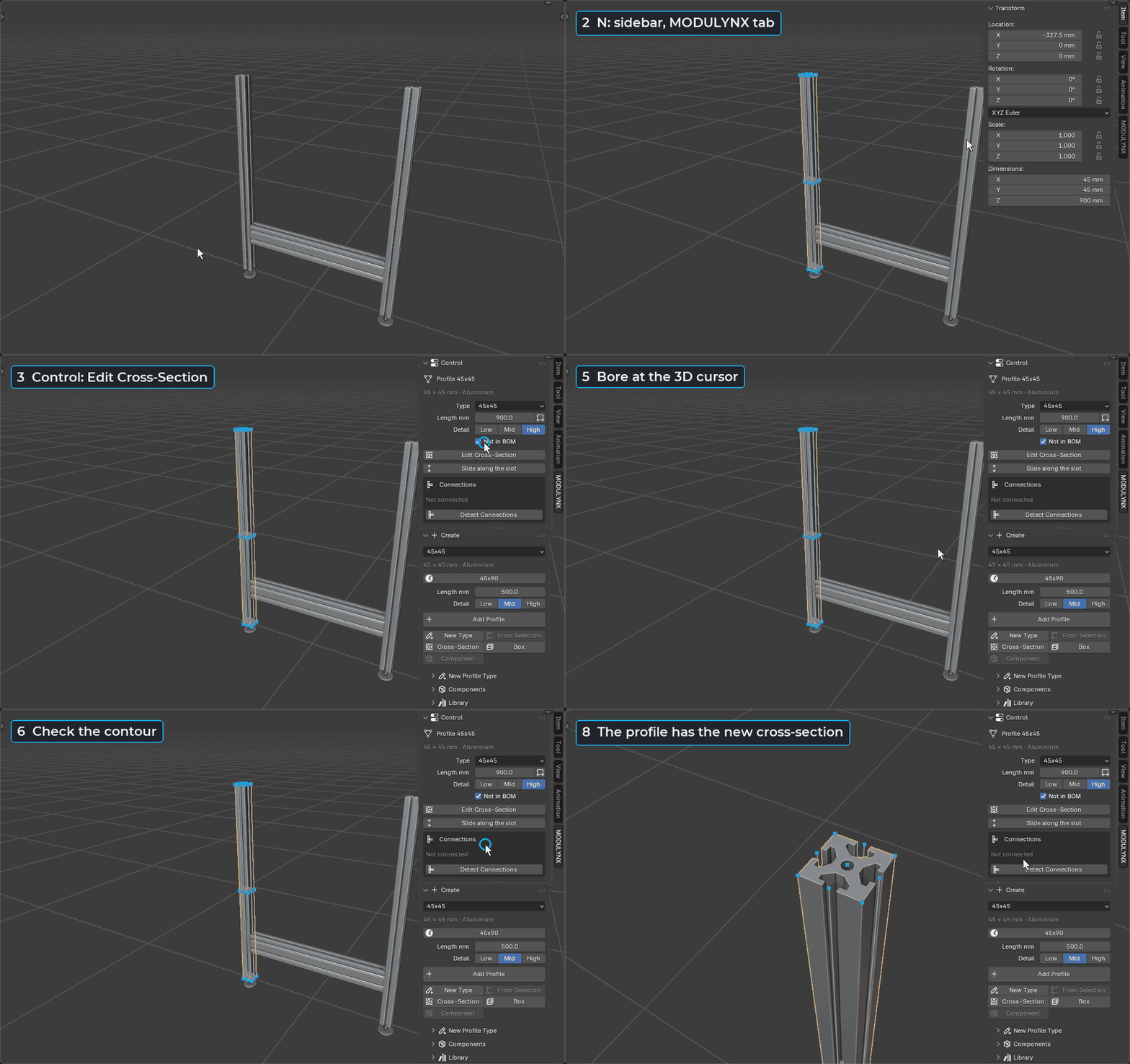
Edit the contour of any profile type with Blender's own tools – add bores, rectangles and T-slots, check the contour and save. Every profile of that type is rebuilt. Or create types from templates, drawn contours and imported manufacturer models.

Editing a cross-section: adding a bore, checking the contour and saving as a new type

WorkflowEverything one key away

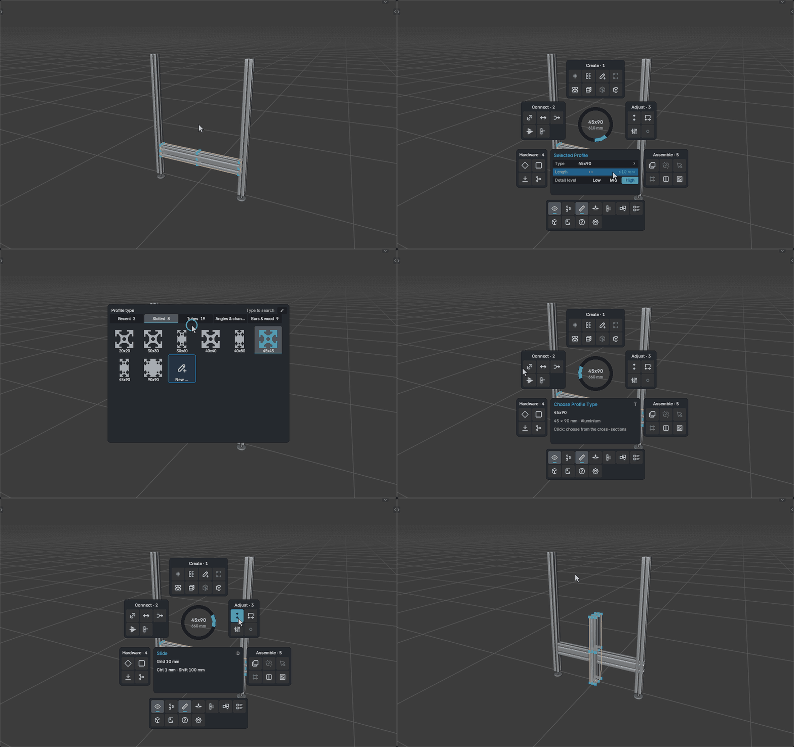
Press P for the radial menu with the active part in the centre – every tool of MODULYNX is in it. The sidebar uses the same groups and icons: Create, Connect, Adjust, Hardware, Assemble, View & Export.

The MODULYNX radial menu with parameter field and the profile type grid
New in MODULYNX 1.0

From the model to the workshop

Version 1.0 takes your frame all the way to production: what to order, what it weighs, what it costs, and files your CAD program and your laser cutter understand. Thank you to everyone who tested the betas.

Components with their own connection nodes
New

STEP for every part

Profiles, panels, components and your own parts open in Fusion, FreeCAD and SolidWorks as real solids. Holes and rounded edges become real cylinders, assemblies stay assemblies.

New

DXF for laser and CNC

Plates, sheets and panels as outlines in mm with real arcs and circles. Holes on their own layer, labels with thickness, material and quantity.

New

Bill of materials with prices

Cut list, connector parts and machining per joint, weight from the real cross-section, price per metre and per cut, a kit quantity – in the sidebar and as CSV.

New

Joints and standard profiles

Choose an angle bracket, an anchor connector or none for each joint. Steel tubes, angles, channels, bars and timber are included with real cross-sections.

New

Collision check

One click selects every pair of parts that penetrate each other. Touching parts and panels in their slots are fine.

Known limits

Still to come

Moving parts with Blender's own G key doesn't make connected parts follow – use the MODULYNX handles. Values in the radial menu's centre field can't be typed yet.

MODULYNX documentation

Getting started

MODULYNX works in Object Mode in the 3D viewport. All lengths are in millimetres.

Installation

  1. Download the ZIP from Gumroad. Don't unpack it.
  2. In Blender 5.2 or newer open Edit › Preferences › Get Extensions.
  3. Open the menu at the top right and choose Install from Disk…, then select the ZIP.
  4. The MODULYNX tab appears in the sidebar of the 3D viewport (N). Press P for the menu.

Updating: install the new ZIP the same way – it replaces the old version. Your settings and your own profile types stay in place.

Your first frame

  1. Add a profile. Sidebar › Create › Add Profile (or P, then N). It appears at the 3D cursor with the type, length and detail level set above the button.
  2. Attach the next one. Connect › Attach, point at a node and click. Move the mouse or press N to pick the direction, R to rotate.
  3. Span between posts. Span takes two nodes and sets the length from their distance.
  4. Fine-tune. Drag the handles of the selected profile, or use Adjust › Slide and Extend.
  5. Add hardware. Hardware places brackets, end caps or levelling feet on end faces.
  6. Group and repeat. Assemble › Group, then Row for shelves at a fixed spacing.
  7. Output. View & Export › bill of materials (CSV), STEP for CAD or DXF for the laser cutter.

Box and panels

Create › Box (P, then O): click the first corner on the floor, drag the footprint and click, drag the height and click. The outer dimensions are the ones you dragged.

  • Ctrl 1 mm grid, Shift 100 mm grid. Type a number and press Enter for exact sizes; Tab switches between width and depth.
  • Mouse wheel: number of rail levels (bottom, top and evenly in between). F: levelling feet.
  • Uses the profile type set under Create. Posts and rails are connected, so they follow each other.

Assemble › Panel (P, then I): point into an opening surrounded by four profiles and click. An infill panel goes into the slots by half the slot depth on each side; M switches to a panel mounted on the frame, the wheel changes the thickness, Shift+click places more. Size, thickness and material can be changed in the Control panel afterwards.

Handles

Select one profile and blue handles appear: arrows at both end faces change the length (the other end stays put), the ring moves the profile along its axis, two side arrows move it across.

  • 10 mm grid, Ctrl 1 mm, Shift 100 mm, Alt grid only.
  • Snaps to nodes of other profiles and to neighbouring faces: flush, resting against, centre on centre, centre on a slot. The label next to the mouse says what it snapped to.
  • Type a number and press Enter for the exact length or offset. Esc cancels, Ctrl+Z undoes the whole drag.

No handles? Turn on Blender's gizmos (viewport header, top right) and check View & Export › Handles.

Connections

Attach, Join, Span and Extend remember which part rests on which profile. The Control panel lists the connections of the selected profile. For older files, Connect › Detect finds end faces that rest on other profiles.

When a profile moves or changes length, the parts connected to it follow: a part resting on an end face moves with it, a rail between two posts gets longer or slides along the post that stays. Turn it off with View & Export › Follow.

Cross-section editor

  1. Select a profile and click Edit Cross-Section in the Control panel (or P, then Q).
  2. The contour opens in Edit Mode, seen from the top with edge lengths. Use G, E, M and Ctrl+Shift+B (round a corner).
  3. Bore and Rectangle add a contour at the selected points or the 3D cursor; T-Slot on Edge cuts a slot into the selected outer edge.
  4. Check Contour finds open contours, crossing edges, contours closer than 0.05 mm and tiny edges.
  5. Save rebuilds every profile of this type. Built-in types are saved under a new name.

Keys in the tools

The current keys are always shown at the bottom left of the viewport while a tool runs. H hides the hints.

KeyAction
ClickChoose or place on a node
Shift+ClickPlace and continue
R / Shift+RRotate 90° / back – 0° is top side up
Mouse / NDirection at the target node
FContact face of the part
Alt+wheelSlide along the slot
Ctrl / ShiftFine (1 mm) / coarse (100 mm)
ESlide: measure from start or end
Ctrl+wheelChange length
Number + EnterType length or offset
TabSwitch the typed value (length / offset, width / depth, distance / copies)
EscCancel

Components

  1. Select any mesh – a mounting plate, a holder, a bracket – and choose Create › Components › Make Component (or P, Create). Its origin moves to the bottom centre.
  2. It gets the node grid of its size, plus a node in the middle of every bore it finds.
  3. Edit Nodes in the Control panel: click on the surface to add a node (it snaps to corners, edge and face centres), X deletes, Enter finishes.
  4. Attach profiles to its nodes like to a profile. Move it with the handles – attached parts follow.
  5. Save to Library keeps it for all your files; Add Component (P, Z) places it at the 3D cursor.

Article number, weight and price of a component go into the bill of materials.

Bill of materials

View & Export › Bill of Materials lists every profile type with its cut lengths, connector parts and machining per joint, panels and components – with weights. Export as CSV writes it for ordering.

  • Joints: set the default connector under Connect (or P, Hardware) and change it per joint in the Control panel. Anchor connectors add a bore, angle brackets add the bracket.
  • Prices: enter a price per metre and per cut for the current type under Create › Library, and a price per component. The total appears below the list and in the CSV.
  • Kits: the kit quantity multiplies the whole list. Not in BOM leaves out parts you already have.

STEP export

Use File › Export › MODULYNX Parts (.step) or View & Export › STEP. Open the file in your CAD program like any STEP file.

  • Parts: the selection (including selected assemblies) or everything visible.
  • Detail level: High is recommended for CAD; "As in scene" keeps each profile's level.
  • Exact arcs: radii, tubes and holes become real cylinder faces instead of facets.
  • Keep assemblies: MODULYNX assemblies become sub-assemblies in CAD.
  • Other parts: components and your own meshes made of flat faces, holes and radii are exported as exact solids too.

Freeform shapes (spheres, subdivision surfaces) and connectors are left out; the report names the skipped objects.

DXF export

View & Export › DXF or File › Export › MODULYNX Flat Parts (.dxf) writes flat parts – panels, sheets and plates, also with holes and rounded corners – as outlines in millimetres for laser, plasma, waterjet and CNC.

  • Rounded corners are real arcs, holes real circles. Layers: OUTLINE, HOLES and LABELS (name, thickness, material, quantity).
  • Identical parts appear once with their quantity, or each piece separately.
  • Profiles can be added as cross-sections, e.g. for end plates.

Parts with steps, pockets or chamfers can't be cut from one outline; they are skipped and named in the report.

Questions

Where are my own profile types stored?

In profiles_user.json in MODULYNX's user folder. Sidebar › Create › Library › Folder opens it. They are shared by all your .blend files; a backup is kept before a type is overwritten or deleted.

Can I use real manufacturer profiles?

Yes. Import the manufacturer's model, select it and choose From Selection under Create – MODULYNX cuts the cross-section from the middle of the part. Article numbers in the name are picked up for the bill of materials.

Which units does MODULYNX use?

Millimetres throughout. MODULYNX reads the scene's unit scale, so it also works in files where one Blender unit is not one metre.

Where are prices and components stored?

In MODULYNX's user folder next to your profile types: prices in prices.json, components in the components folder. They are shared by all your .blend files.

Where do I report a bug or suggest a feature?

On the Discord. A screenshot and your Blender version help a lot.

Planned · MODULYNX 1.1

What comes next

These features are planned for the next version, not released yet.

Planned

Stretch

Drag a plane through the frame and every profile crossing it gets longer or shorter.

Planned

Follow with G

Connected parts follow when you move with Blender's own tools too, including rotations.

Planned

More connectors

Cube and corner connectors, brackets placed as parts automatically, real manufacturer article numbers.

Planned

More frame tools

Components with previews in the radial menu, centre posts in the box tool, fences along a path.

Want news about new versions by e-mail? Follow MODULYNX on Gumroad.

Follow on Gumroad

In development. Not available yet – follow the progress on Discord.

ROUTELYNX · prototype

Cables that know their bend radius

ROUTELYNX follows the workflow of CAD harness tools: place pins on your parts, lay segments through the model, connect pin to pin – the wires find their way through the segments. Everything below works in the current prototype; names, details and the release date can still change.

  • Pins on any part – drag them over its faces, rename or flip them. MODULYNX nodes work as pins too.
  • Segments through work points on faces, at pins or free in space, as a smooth spline or as straight runs with guaranteed radii.
  • Automatic routing along the shortest path, or exactly through the segments you pick.
  • Multi-core cables: the jacket runs as one, the cores go to their own pins at the stripped ends. Splices on segments.
  • Checks and numbers: bundle diameter, minimum bend radius per wire, cut lengths, wire list as CSV, one bill of materials with MODULYNX.
  • Realistic view with twisted bundles and cable ties, for renderings. Move a part and the harness follows.

ROUTELYNX can't be bought or downloaded yet. Want to see it early or tell us what you route? Say hi on Discord.

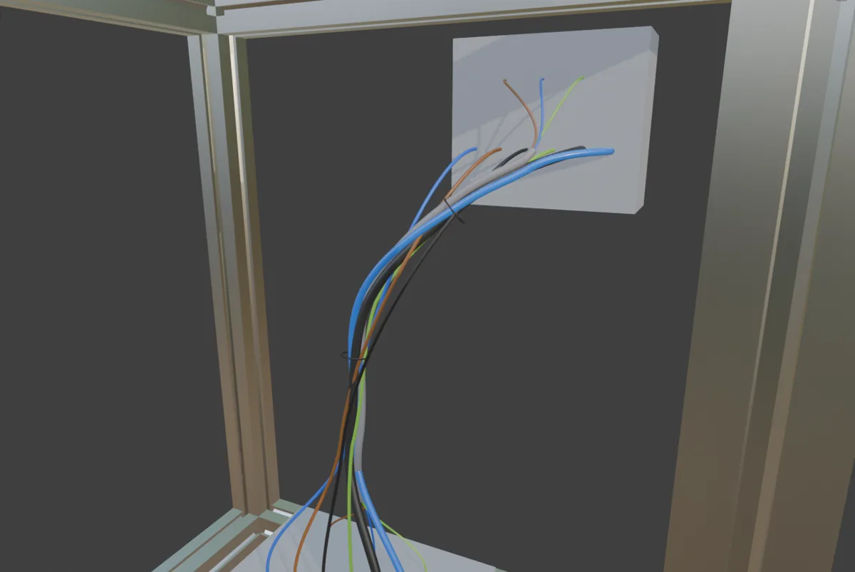
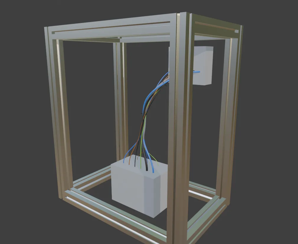
ROUTELYNX prototype, realistic view: a bundle of blue, brown, black and green-yellow wires, a grey cable and a hose with cable ties, fanning out into a junction box ROUTELYNX prototype: a harness from a control box up to a junction box inside a MODULYNX aluminium frame
Community

Build FORMLYNX with us

  • New versions and devlogs before anyone else
  • Feature requests and bug reports straight to the developer
  • Help with your own racks, frames, machines and harnesses
  • Early looks at ROUTELYNX
Join the Discord discord.gg/8xnfEfXbew

Get MODULYNX on Gumroad. Support the development on Ko-fi.